Okay, so I knew I would be back... I added in two new features. A rotating warning/hazard light and a steam particle system. I've also remove one of the transitions in my turntable video and slowed it down slightly.
Game Art & Design
Showing posts with label BA3 - Project 2. Show all posts
Showing posts with label BA3 - Project 2. Show all posts
Sunday, 20 May 2012
Sunday, 13 May 2012
#075 GAD BA3 - P2: Poly Clean-up
Having finished fairly early, and feeling guilty about seeing other people working so late at night, I decided to go through my entire model and clean it up. I set myself the challenge or removing ALL tris in my model so that I was only left with quads. After a lot of crashing, swearing and screaming... I managed it!
My model has 2335 faces, and 4670 tris. From this (as well as looking all over my model) confirms that I have no tris, only quads in my model: 2335 faces x amount of tris in a quad (2) = 4670.
I went through each object one by one, cleaning up any stray vertexes I found (only 1 or 2) as well as dividing up faces to create quads. It was not so difficult, just a bit of a brain teaser to see how to fit quads into different faces with varying edges. I know that we didn't have to be so meticulous about it, in fact we were told that a few tris here and there won't cause too many problems... But it is good practise.
... and with that. I am done with BA3 P1-2... or am I?
Saturday, 12 May 2012
#074 GAD BA3 - P2: Turntable Final
After a lot of tweaking, stressing and lots of coffee, here is my final turntable piece. Instead of just having the finished model in a 180 view, I wanted to show the stages building up as model turns from side to side. Below are the stages and what they include.
Stage 2: Textures and Shadow Map
Stage 3: Textures, Shadow Map and Bump Map
Stage 4: Lighting, Textures, Shadow Map and Bump Map
and with that, I now conclude my BA3 Project 1 and 2.
#073 GAD BA3 - P2: Lighting and Shadows
Probably one of the hardest parts so far, lighting the model accurately. For me, because I have 4 wall lights (two on each side) I will need to have at least 4 light sources. I started off by looking at point lights, which did not work so well. I then moved on to ambient lights, which again did not work so well. I then found the spot lights, which with a bit of tweaking started to look fairly good. I changed the colour of the light to a very light yellow, reduced the intensity down to 0.3, as well as increased the Cone Angle to 130 degrees. I matched the Cones edges up to the light fitting, so that the light shone out of the actual light object. After a bit of testing and tweaking I settled on a drop off of 5, which lit the centre of the room but not the walls. To light the walls I placed two ambient lights in the middle of the room, one a bit further down the X axis than the other. I turned their intensity down pretty low, as I only wanted them to just about light the walls and ceiling.
With all the lights, there were a lot of shadows on my model. To fix this I began to experiment between having shadows turn on or off on the two types of lights. Logically speaking, I should of had the shadows coming from the spot lights on the walls, however the shadows they produced looked untidy and a bit unnatural. So, putting logic aside, I went with what was more aesthetically pleasing. I used the two ambient lights in the middle of the room to cast the shadows as they produced the best looking and most tidy shadows.
The next thing I did was add a glow to the actual light objects. I spotted this while working on a personal project, so I had kept it in mind when creating the lights for this project. I gave them a glow intensity of 0.5 and changed the colour to have a slight yellow tint.
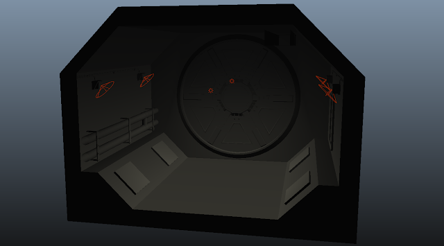 |
| 6 lights in total: 2 Ambient Lights and 4 Spot Lights. |
 |
| Lighting and Shadows, No texture. |
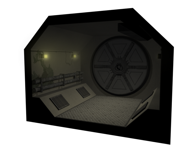 |
| Lighting, Shadows and Texture. |
Friday, 11 May 2012
#072 GAD BA3 - P2: Bump Mapping
While bump mapping was not necessary, I thought I would take a crack at it (in the easiest way). I watched a short video on the basic bump mapping using white, grey and black which gave me the basic knowledge (shown below).
Maya: Basics of Bump Mapping:
http://www.youtube.com/watch?v=y5MGaoQ9JSI
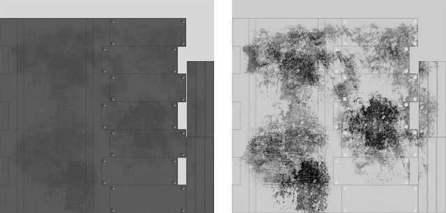
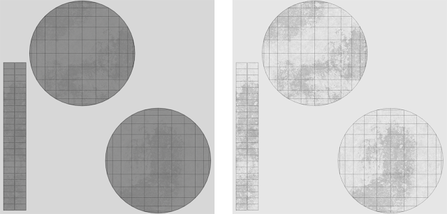
From my understanding, if you have a neutral background (grey), then any areas in white are pulled out and any area in black is pushed in. I know that there are much better ways of doing it using Mudbox, but for the sake of showing that I understand the basics of bump mapping I will just use Photoshop. Results are shown below:
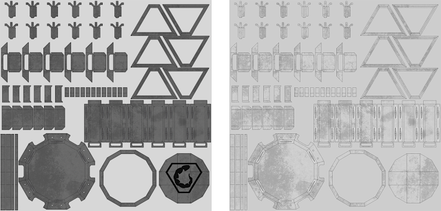 |
| Door Pieces: Texture and Bump Map Images |
 |
| Geared Bolt: Texture and Bump Map Images |
 |
| Main Door Piece: Texture and Bump Map Images |
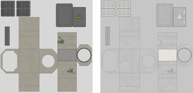 |
| Tunnel Piece: Texture and Bump Map Images |
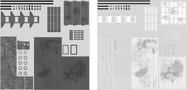 |
| Tunnel Props: Texture and Bump Map Images |
Thursday, 10 May 2012
#071 GAD BA3 - P2: Turntable Preview
So here is the turntable preview of my door. I still need to add bump mapping, lighting, as well as some shadow maps. Getting there though...
#070 GAD BA3 - P2: UV Mapping & Texturing Continued
Speaking to a few of my peers, I noticed that I had quiet a lot of UV Maps/Textures... In fact, I had a lot more than the norm. As it stood, I had 14 UV Maps/Textures, which was way too much considering we are meant to be producing an efficient model.
So, I got back in to Maya and made some changes. I began to combine the UV's of multiple objects, creating a much tighter, compact UV Map. I then took these UV Maps into Photoshop and began re-making the textures to map multiple objects at the same time. Below is what I have done:
So, I got back in to Maya and made some changes. I began to combine the UV's of multiple objects, creating a much tighter, compact UV Map. I then took these UV Maps into Photoshop and began re-making the textures to map multiple objects at the same time. Below is what I have done:
 |
| All front door pieces included apart from the geared bolt pieces, which are seperate. |
 |
| The main door piece: I kept this separate as it is one of the larger objects and I wanted the metal detail to be nice and clear. |
 |
| The tunnel piece: Now includes the electricity box. I still kept it fairly large for the same reasons as the main door piece, quality. |
 |
| All the props: Sewage Pipe, Sewage Pipe Brackets, Light Fittings, Wires, Wire Brackets, Air Vent. |
 |
| The Light: I've kept this separate from the other pieces as I want to add a glow to the object to simulate lit glass. |
 |
| The Geared Bolts: I've kept these septate as they will be animated when the door unlocks itself. |
Friday, 4 May 2012
#069 GAD BA3 - P2: UV Mapping & Texturing
Probably the most aggravating part of this project was the UV Mapping. In total I had to do 14 UV Maps, including the 7 UV Maps for the scenery which I found we had to do at the last moment. All the UV Maps are unfolded (as much as they could be), so that the textures run smoothly over edges and corners.
I won't explain how I did each of them, as I can pretty much explain how I did all of them at once. I used a mixture of the automatic mapping tools (planar, cylinder, automatic) depending on the faces of the object. Some of the pieces were fairly easy and just required the automatic mapping tool, while with others I had to select separate faces and use the planar or cylinder mapping tool (while making sure they were all on a identical scale). Once all the faces were mapped I then began to sew the edges together, I soon found that this was not as easy as I first thought. I realise that not all of the UV Maps could not be fully unfolded and required some of its faces to be separated from the main section otherwise they would overlap with other faces. Because of this I had to work out how which pieces could be fitted together and how I could fit them together to create the most efficient unfolded map. Some pieces are deliberately separated to prevent bleeding of the textures when I add them.
Below I have organise images in the format from left to right of: Object, UV Map, UV Map & Texture. The object name is included in the caption.
 |
| 1# Geared Bolt |
 |
| 2# Primary Bolt Holder |
 |
| 3# Secondary Bolt Holder |
 |
| 4# Central Locking Mechanism |
 |
| 5# Decorative Handle |
 |
| 6# Decorative Triangular Panel |
 |
| 7# Main Door Structure |
 |
| 8# Light Fitting |
 |
| 9# Light |
 |
| 10# Electrical Wires |
 |
| 11# Sewage Pipe |
 |
| 12# Air Duct |
 |
| 13# Electricity Box |
 |
| 14# Scenary Structure |
Wednesday, 2 May 2012
#067 GAD BA3 - P2: Maya - UV Mapping Tutorial
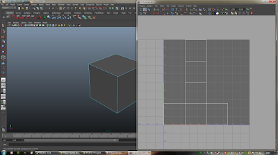
As I said, today we were given a more detailed tutorial in UV mapping. Below I will walk through the stages completed as well as the tools used.
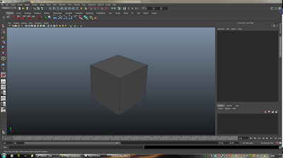 |
| Step 1: Create a Poly Cube. |
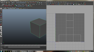 |
| Step 2: Open up the UV Texture Editor with the cube selected. |
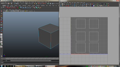 |
| Step 3: You can separate the pieces by selecting the lines and using the "Separate UV" tool. |
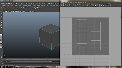 |
| Step 4: You can re-connect the lines by using the "Sew UV" tool, which automatically moves and links the UV groups together. |
 |
| Step 5: As shown above, all the pieces are stitched back together. |
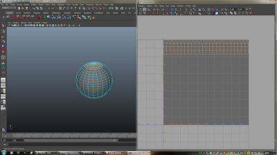 |
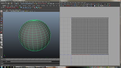
| Step 7: Select the top section of the sphere. |
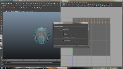 |
| Step 8: Create a Planar Map along the Y axis. |
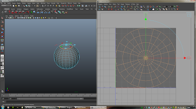 |
| Step 9: Adjust the Planar map to fit the sphere. |
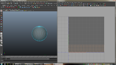 |
| Step 10: Select the lower section of the sphere. |
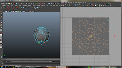 |
| Step 11: Create a Planar Map along the Y axis again. |
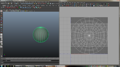 |
| Step 11: Select the entire sphere with Object Mode. |
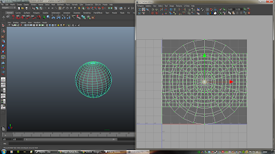 |
| Step 12: Select all the UV pieces with the Shell Tool |
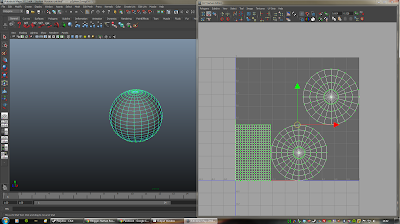 |
| Step 13: Use the Layout tool to automatically adjust the pieces to fit the area better. |
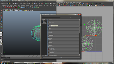 |
| Step 14: Right click the sphere, select "Assign New Material" and click Lambert |
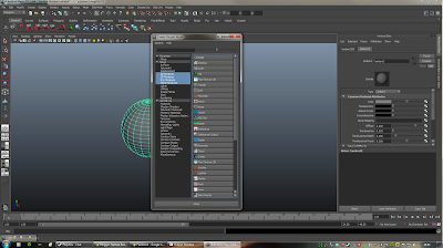 |
| Step 15: In the Attribute editor click the black and white icon next to colour, then select "Checker". |
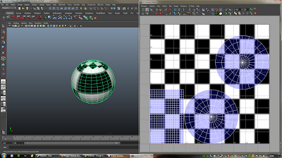 |
| Step 16: At the moment the texture is still a bit distorted, this is because the UV pieces are different sizes. |
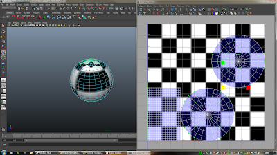 |
| Step 17: To fix this, select the Scale tool from the main panel and scale the squared block up. |
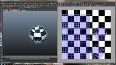 |
| Step 18: As you can see, the scale of the texture is now much better on the sphere. |
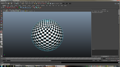 |
| Step 19: You can scale the image down even more, giving the above effect. |
Tuesday, 1 May 2012
#068 GAD BA3 - P2: Materials & Rendering Fundamentals
Carrying on from P1: Digital Modeling, P2:Materials & Rendering Fundamentals involves adding materials and rendering our door models in to a pre-built game engine. The brief takes us through texturing, UV mapping, hypershading, bump mapping and rendering of our models.
We had a class tutorial on the Monday, sort of brushing over the basics of what we needed to do. Mark used a cube as an example and showed us how the UV mapping works. At first it looked a bit daunting, like most of Maya... However once he showed us the basics it did not seem as bad as my first impression.
Tomorrow should be a bit more of an eye opener, we have a group tutorial where we will be taken through the process in more detail.
Subscribe to:
Posts (Atom)

